High-Frequency PCB
High Frequency PCB (RF & Microwave)
high-quality High Frequency PCBs, available in Rogers and PTFE Teflon materials, with a 2-layer option. Fast 4-5 day turnaround and industry-leading quality assurance.
What is High Frequency PCB?
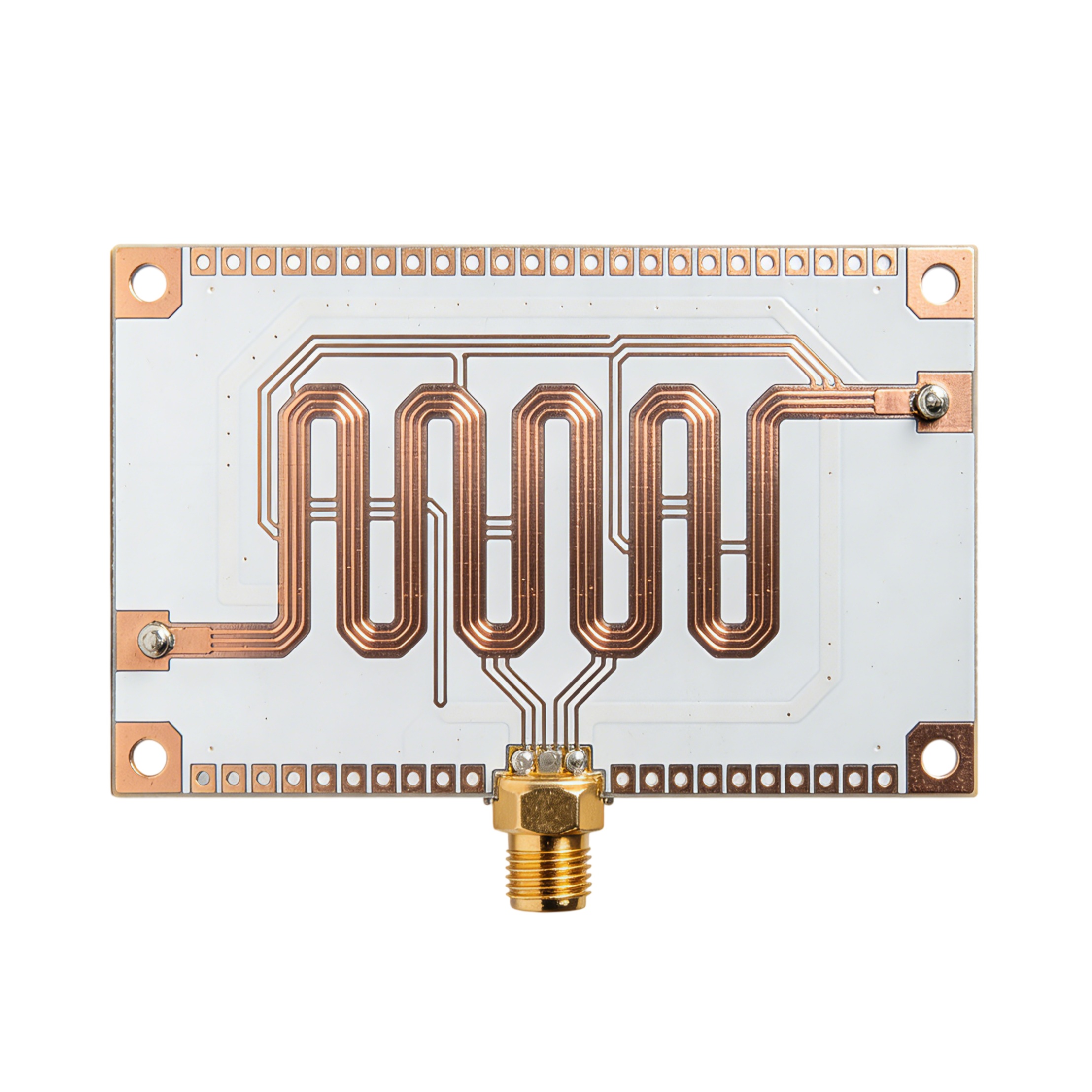
High Frequency PCB, often referred to as RF (Radio Frequency) or Microwave PCB, is a specialized circuit board designed to transmit electromagnetic signals in the frequency range of 500MHz to 100GHz+.
As the frequency increases beyond a certain limit, signal losses in standard FR4 boards rise significantly. To address this, we offer a range of High-Frequency PCBs, designed specifically for MHz to GHz applications. These boards use low-loss dielectric materials with a reduced loss tangent, minimizing signal degradation. This ensures controlled electromagnetic interference (EMI) and reliable, high-speed signal transmission.
Common Materials of High Frequency PCB
Unlike standard FR4 boards, High-Frequency PCBs can be selected based on Dk (dielectric constant) and Df (dissipation factor). The lower these values, the better the signal integrity at high frequencies. Some materials that RUNHI offers as below:
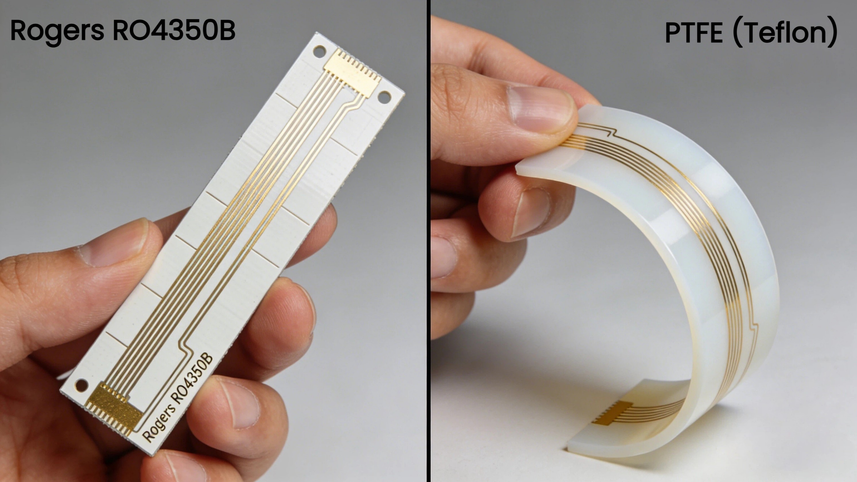
- PTFE (Teflon) Based: (e.g., Rogers RT/duroid series). These offer the lowest possible signal loss but require specialized manufacturing processes like plasma etching for via plating.
- Ceramic-Filled Hydrocarbon: (e.g., Rogers RO4000 series). These materials offer excellent high-frequency performance while being easier to process (similar to FR-4), making them a cost-effective choice for many commercial applications.
Feature | Rogers RO4350B (Ceramic-Filled Hydrocarbon) | PTFE (Teflon) Based (e.g., Rogers RT Series / Taconic) |
Dielectric Constant (Dk) | Stable (3.48), Ideal for standard RF designs. Consistent performance up to 40GHz. | Ultra-Low (2.20), Lowest possible Dk for maximum signal propagation speed. |
Dissipation Factor (Df) | Low (0.0037 @ 10GHz), Excellent for 4G/5G, Power Amplifiers, and standard Radar. | Ultra-Low (0.0009 @ 10GHz), Required for Millimeter-wave & extreme low-loss applications. |
Processability | Standard (Like FR-4), Rigid material. Compatible with standard PCB lines. Lower fabrication cost. | Complex (Specialized), Soft material. Requires Plasma Etching or Sodium treatment for via plating. |
Mechanical Rigidity | High (Rigid), Easy to handle during SMT assembly. Excellent for Multilayer stacks. | Low (Soft/Pliable), Can deform under stress; requires careful handling during assembly. |
Thermal Coefficient (TCDk) | Excellent (50 ppm/°C), Dk remains stable over wide temperature ranges. | Good, However, high Z-axis expansion (CTE) can risk plated through-hole reliability. |
Hybrid Capability | Excellent, Bonds perfectly with FR-4 prepregs. Ideal for cost-effective Hybrid Stack-ups. | Difficult, Material incompatibility makes hybrid lamination challenging and expensive. |
Cost | Moderate - High, Best performance-to-cost ratio for volume production. | Very High, Premium raw material + Higher processing cost. |
The Benefits of High Frequency PCB
- Low Dielectric Loss: Lower loss in PCB dielectric means higher signal strength. Dielectric losses can cause EMI failure and excessive crosstalk. With a low dissipation factor (Df), signal losses can be controlled at high frequencies.
- Tight Impedance Control: The stable Dielectric Constant (Dk) over a wide frequency and temperature range ensures precise impedance matching (usually 50Ω), preventing signal reflection.
- Moisture Resistance: High-frequency materials absorb very little moisture (unlike FR-4). Since water has a high Dk, low absorption is critical for maintaining performance in humid environments.
- Thermal Stability: Many RF materials have a low coefficient of thermal expansion (CTE), ensuring the board remains reliable during extreme temperature cycling in aerospace or outdoor applications.
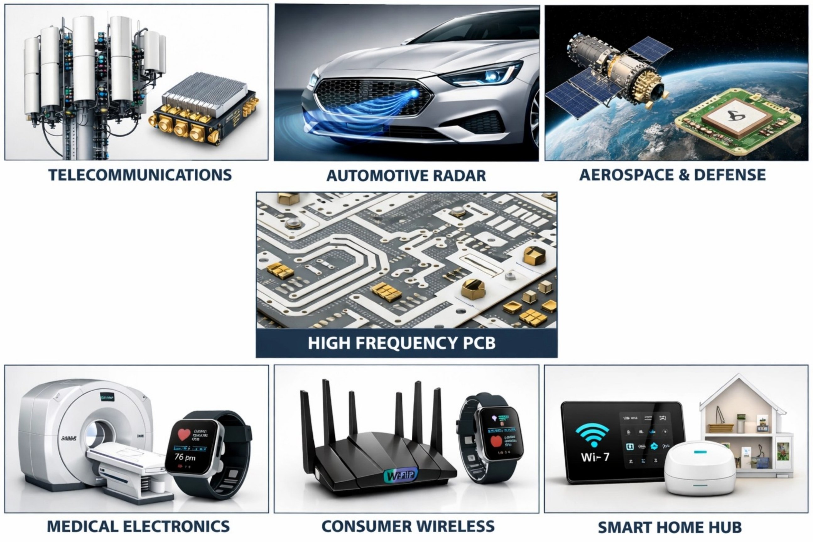
Common Applications of High Frequency PCB
These boards are the engines of modern communication and detection systems:
- Telecommunications: 5G Base Stations, Power Amplifiers, Filters, Combiners.
- Automotive Radar: 77GHz Millimeter-wave radar for collision avoidance and autonomous driving.
- Aerospace & Defense: Satellite communications, GPS antennas, Military guidance systems.
- Medical Electronics: MRI systems, Wireless patient monitoring devices.
- Consumer Wireless: High-end Wi-Fi 6/7 routers, Smart home hubs.
Why Choose RUNHI as Your High Frequency PCB Manufacturer?
- High-Frequency Performance: RUNHI offers High Frequency PCBs using advanced materials like Rogers RO4350B and PTFE Teflon, delivering low-loss performance with a Dk of 2.55-3.48 and Df as low as 0.0016. These materials ensure exceptional signal integrity for high-speed applications from 1GHz to 40GHz.
- Reliable Quality Assurance: Our industry-leading quality assurance process guarantees that each PCB undergoes rigorous testing, ensuring reliable and consistent performance at high frequencies. RUNHI maintains high standards, so you can trust your designs to perform under demanding conditions.
- Fast Prototyping: With a 4-5 day prototyping turnaround, RUNHI ensures fast delivery without sacrificing quality, so you can iterate and refine designs quickly.
RUNHI Technical Capabilities (High Frequency)
Feature | Capability Specification |
Base material | Rogers, PTFE Teflon |
Dielectric Constant (Dk) | 2.2 to 10.2 (Tolerance ±0.05) |
Dissipation Factor (Df) | 0.0009 - 0.0035 |
Layer Count | 2 Layers |
Min. Trace/Space | 3mil / 3mil (0.075mm) |
Surface Finishes | ENIG |
Board Thickness | 0.51mm/0.76mm/1.52mm for Rogers PCB
0.76mm/1.52mm for PTFE Teflon PCB |
Minimnum Track Width and Spacing | 0.10 / 0.10 mm (4 / 4 mil) |
Minimum Dimensions | 3 × 3mm |
Maximum Dimensions | 590*438mm |
Copper Weight | 1oz |
Soldermask Color | Green |
Silkscreen | White |